


The GRUNDIG SUPER COLOR 6065 is a 26 inches color television particular model.
- It's first models series with the INLIne PHILIPS 20AX CRT TUBE Introduced in 1975.
- It's first model With CLOCK TIME FEATURE OSD.
- It's first GRUNDIG model with Ultrasonic remote control system in a Set with PHILIPS 20AX CRT TUBE
but with potentiometric tuning search.
The invention relates to a tuning unit with bandswitch for high frequency receivers, especially radio and television receivers, having a potentiometer system for the control of capacity diodes, the said potentiometer system consisting of a plurality of parallel resistance paths along which wiper contacts can be driven by means of screw spindles disposed adjacent one another in a common insulating material housing in which a bandswitch formed of metal rods is associated with each tuning spindle.
In these tuning units, the working voltages of the capacity diodes in the tuning circuits are recorded once a precise tuning to the desired frequency has been performed. A potentiometer tuning system has great advantages over the formerly used channel selectors operating with mechanically adjustable capacitors (tuning condensers) or mechanically adjustable inductances (variometers), mainly because it is not required to have such great precision in its tuning mechanism.
Tuning units with bandswitches formed of variable resistances and combined with interlocking pushbuttons controlling the supply of recorded working voltages to capacity diodes are known. Channel selection is accomplished by depressing the knobs, and the tuning or fine tuning are performed by turning the knobs. The resistances serving as voltage dividers in these tuning units are combined into a component unit such that they are in the form of a ladderlike pattern on a common insulating plate forming the cover of the housing in which the tuning spindles and wiper contacts corresponding to the variable resistances are housed. The number of resistances corresponds to the number of channels or frequencies which are to be recorded. The wiper contact picks up a voltage which, when applied to the capacity diodes determines their capacitance and hence the frequency of the corresponding oscillating circuit. The adjustment of the wipers is performed by turning the tuning spindle coupled to the tuning knob. By the depression of a button the electrical connection between a contact rod and a tuning spindle is brought about and thus the selected voltage is applied to the capacity diodes. Since the push buttons release one another, it is possible simply by depressing another button to tune to a different receiving frequency or a different channel, as the case may be.
In the end of the 60's increasingly attention was focused on the varicap diode tuner as the latest, sophisticated means of television receiver frontend tuning in both colour and black and white sets.
The main purpose of this article is to investigate the servicing problems associated with this comparatively new method of tuning.
First however let's briefly recap on the principles involved in this tuning system:
The tuners use variable capacitance (or "varicap") diodes as the variable tuning elements: the effective capacitance of the diodes is controlled by the reverse bias applied across them, tuning being achieved by varying this voltage. As the reverse bias across a varicap diode is increased so its junction depletion region widens thus reducing its capacitance.
A VHF/ UHF television tuner is constructed in accordance with the present invention includes a preselector tuned circuit having a solid state voltage controlled capacitor as its tunable element, a radio frequency amplifier coupled to the preselector circuit and alsoother circuit to perfect the signal receiving capability and the application the like.
Considering the Mechanical Tuner Problems:
To get the servicing problems in perspective let us next consider the tuning arrangements previously used.
The earliest of these, employed on v.h.f., was the switched tuner which was either of the turret or incremental type.
The turret tuner substituted a coil bearing "biscuit" mounted on the rotating drum or turret when channels were changed. Twelve positions were normally provided, with a fine tuning knob to adjust the local oscillator frequency. As its name suggests the incremental tuner simply added more inductance to the tuned circuits at every downward channel movement: thus the highest inductance was present on channel one and the least on channel 12 (which normally covered 13 as well with manipulation of the fine tuner).
The movement towards u.h.f. TV working, initially with dual standard sets and later with single standard ones, brought about the need for u.h.f. tuners. In the earliest u.h.f. receivers valve tuners which were not particularly efficient were used.
The drive mechanism was usually a dual speed rotary system calibrated from channels 21 to 68. Experience in the field indicated that 625 line television was in many cases considered by the viewer to be inferior to 405 -line reception, on account of the poor signal to noise ratio achieved by the valve tuners. Many viewers were not prepared to use external u.h.f. aerials of course, having achieved satisfactory reception on v.h.f. with an indoor aerial: this aggravated the situation even more.
Another aspect which caused difficulty was the care needed to tune in a u.h.f. channel using a rotary tuner covering the whole of Bands IV and V. Many viewers simply could not tune in BBC 2 or ZDF or ORF or any channel correctly with such a tuning mechanism, finding that they had passed right over the channel they wanted before realising what they had done.
The advent of transistor tuners rapidly improved the quality of u.h.f. reception but use of a rotary mechanism was continued by many manufacturers. Thus while potential reception was improved the same tuning difficulties remained and viewers continued to gravitate towards 405 line viewing using the "old faithful" switched tuner. The operational breakthrough came with the introduction of the push-button u.h.f. channel change.
The mechanism is basically simple. Adjustable push buttons press down on a lever bar which in turn rotates the tuner's variable capacitors to the appropriate position. Each button is capable of tuning over the entire u.h.f. bands and this leads to customer confusion at times when after some adjustments which were too heavy handed they find themselves receiving ITV on a BBC button or a ORF and ZDF broadcasting or any channel possible !
Mechanical Faults:
Mechanical tuning obviously has its snags. There are for example contact springs which earth the tuning capacitor and go intermittent. This gives rise to the most random tuning defects, capable of driving the. most patient viewer to a state of total exasperation. It is also possible for the rotation mechanism to hang up and jam intermittently, or just become sticky, so that the reset accuracy of the mechanism is impaired and the receiver has to be retuned every time the channel is changed.
The vanes in the tuning capacitor can also short out at different settings, thereby eliminating some channels. The Varicap Tuner It will be seen then that mechanical defects can cause very irritating fault symptoms. If one thinks along the lines that anything mechanical is nasty, then the elimination of mechanical parts can only be to the good.
The logic of this is splendid provided the electronic replacement for the mechanical system is more reliable! Otherwise we are leaping out of the frying pan into the fire! In the light of experience gained with mechanical tuning devices it seems great that with the varicap tuner we have at last dispensed with the dreaded rotary tuning capacitor, replacing it instead with a variable voltage to the tuner.
Let us think about this however since things are never quite as simple as they first appear. The tuning voltage has to be variable in order to tune the receiver. Obviously then a means of varying the voltage has to be provided to act as the tuning control.
As it is a voltage that has to be varied the tuning control takes the form of a potentiometer., Now we have returned to a mechanical system again, though in a less complex form.
A potentiometer is required for each channel, selected by pressing the appropriate channel button.
We have lost a tuning capacitor and its rotating mechanism and gained a set of pots and selector switches therefore. Provided the pots and switches are mechanically more reliable than the tuning capacitor we should be better off-or should we?
Need for Voltage Stabilisation.
The voltage selected by the pots cannot be allowed to drift otherwise the receiver will go off -tune. The voltage supply to the potentiometers has to be stabilised therefore and a stabilising zener diode or integrated circuit (TAA550) .is needed for this purpose.
Any failure in this part of the circuit will give rise to tuning drift or worse, a total loss of reception. A short-circuit TAA550 for example will completely remove the tuning voltage while if it is open circuit the tuning can vary with picture brightness. Likewise any intermittency in the potentiometers or associated switching and/or resistors can also cause problems.
Relative Reliability of Tuners:
It will be seen then that in order to lose our troublesome mechanical arrangement we have had to introduce considerably more electronics which we trust are going to be more reliable. In addition we have not so far considered the relative reliability of the varicap tuner itself compared with the mechanical type. Since two r.f. transistors are generally used to compensate for the reduced Q of the varicap tuned circuits we immediately have twice the likelihood of an r.f. stage breaking down!
And being semiconductors the varicap diodes themselves are more likely to fail than the sections of a ganged tuning capacitor. It is reasonable then to conclude that if mechanical faults are the most prevalent the use of varicap tuners will make life easier. Mechanical faults are generally not too difficult to sort out however and the field engineer can often cope with them in the home.
Can the same be said of the varicap tuner? It seems that this type of tuner does not need so much attention as its mechanical counterpart but is likely to throw up some much more difficult faults when it does, resulting in bench repairs being needed. So far my own experience has indicated that varicap tuning faults nearly always need servicing on the bench.
Generally speaking it seems true to say that varicap tuners themselves are adequately reliable: the snags result from the tuning system and stabilised power supply.
Tuning Drift with Varicap Tuners:
If a varicap tuned receiver is constantly drifting off tune the +30V supply should be the number one suspect. It is best to connect an Avometer permanently to the supply so that it can be precisely monitored-if necessary write down the exact voltage measured.
If the receiver drifts, check the voltage. If it has changed, even slightly, this may well be enough to be the cause of the fault. To pinpoint and confirm the diagnosis aerosol freezer should be applied to the stabiliser i.c. or zener. If the voltage returns to normal or changes wildly for the worse the stabiliser is almost certainly the cause of the trouble and should be replaced.
A prolonged soak test should then be carried out. Another point concerning varicap tuners arises with their use in colour receivers.
There were makers of the most expensive colour receiver on the market still didn't use a varicap tuner but instead use a mechanical one. The makers' claim is that the signal to-noise ratio of the varicap tuner is inadequate for their colour standards. Undoubtedly the results obtained on the receiver seem to confirm this. Interestingly, the same manufacturers use varicap tuners in their black -and -white receivers, and the tuning button system is often full of troublesome intermittent contacts. The varicap tuner has its advantages and disadvantages then. Probably the simplest comment would be to say that when it is good it is very very good but when it is bad it is horrid!
The PHILIPS 20AX system was introduced in Europe in 1975 as the first self converging picture tube/deflection coil, combination for 110° degree deflection and screen sizes up to 26". The system is based on the automatic convergence principle discovered by Haantjes and Lubben of Philips Research Laboratory more than 20 years ago. It makes use of an in-line gun array in conjunction with a specially designed saddle type deflection coil. Residual small tolerance errors are compensated by a simple dynamic four-pole system. The tube is 2 cm shorter than conventional 110° Degree tubes and has a standard 36.5 mm neck in order to obtain good color selection. A slotted mask is used in combination with a stripe-structure screen. Picture sharpness is ensured by an astigmatic electron gun.
The
new tube, to be known as the 20AX, has been developed by PHILIPS in
conjunction with the parent Philips / Mullard organisation and will be
produced by several Philips subsidiary companies on the Continent as
well as by PHILIPS in the UK. PHILIPS envisage quantity production of
the tube by 1976, mainly for export at first, with large-scale
production for UK set - makers starting in 1977. The tube has been
developed as "probably the final phase in the design of the 110°
shadowmask tube". Its 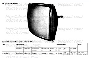 main
features are the use of three guns mounted horizontally in line, the
use of a shadow - mask with slots instead of circular holes, and a
screen with the phosphors deposited in vertical stripes instead of as a
pattern of dot triads. It seems therefore that the days of the present
delta gun shadowmask tube are now numbered, though considerable
production will have to continue for many years to provide replacement
tubes for the millions of colour sets already in use. So far as the
viewer is concerned however it is important to appreciate the time scale
involved (see above) and the reasons for the development of the new
tube. There is nothing wrong with the type of shadow - mask tube we have
known since the beginning of colour TV: it is able to provide superb
pictures. But in its 110° form it does require rather a lot of
scan/convergence correction circuitry. If this can be reduced by means
of an alternative approach
main
features are the use of three guns mounted horizontally in line, the
use of a shadow - mask with slots instead of circular holes, and a
screen with the phosphors deposited in vertical stripes instead of as a
pattern of dot triads. It seems therefore that the days of the present
delta gun shadowmask tube are now numbered, though considerable
production will have to continue for many years to provide replacement
tubes for the millions of colour sets already in use. So far as the
viewer is concerned however it is important to appreciate the time scale
involved (see above) and the reasons for the development of the new
tube. There is nothing wrong with the type of shadow - mask tube we have
known since the beginning of colour TV: it is able to provide superb
pictures. But in its 110° form it does require rather a lot of
scan/convergence correction circuitry. If this can be reduced by means
of an alternative approach
 main
features are the use of three guns mounted horizontally in line, the
use of a shadow - mask with slots instead of circular holes, and a
screen with the phosphors deposited in vertical stripes instead of as a
pattern of dot triads. It seems therefore that the days of the present
delta gun shadowmask tube are now numbered, though considerable
production will have to continue for many years to provide replacement
tubes for the millions of colour sets already in use. So far as the
viewer is concerned however it is important to appreciate the time scale
involved (see above) and the reasons for the development of the new
tube. There is nothing wrong with the type of shadow - mask tube we have
known since the beginning of colour TV: it is able to provide superb
pictures. But in its 110° form it does require rather a lot of
scan/convergence correction circuitry. If this can be reduced by means
of an alternative approach
main
features are the use of three guns mounted horizontally in line, the
use of a shadow - mask with slots instead of circular holes, and a
screen with the phosphors deposited in vertical stripes instead of as a
pattern of dot triads. It seems therefore that the days of the present
delta gun shadowmask tube are now numbered, though considerable
production will have to continue for many years to provide replacement
tubes for the millions of colour sets already in use. So far as the
viewer is concerned however it is important to appreciate the time scale
involved (see above) and the reasons for the development of the new
tube. There is nothing wrong with the type of shadow - mask tube we have
known since the beginning of colour TV: it is able to provide superb
pictures. But in its 110° form it does require rather a lot of
scan/convergence correction circuitry. If this can be reduced by means
of an alternative approach
as
with the 20AX tube considerable benefits in set production and
servicing will be obtained. This has been the aim behind the development
of the new tube, and the demonstration tube we have seen operating with
its associated deflection yoke and circuitry gave a picture every bit
as good as we have come to expect from the present "conventional"
approach to colour tube design. There are now four colour tubes with in
-line guns, the Sony Trinitron (the first to come along), the RCA /Mazda
PIL tube, the Toshiba RIS tube and now the PHILIPS 20AX. It is
interesting to compare them. The Trinitron is a 90° narrow neck (29mm)
tube. It differs from the others in using an aperture grill (slits from
top to bottom) instead of a mask behind the screen to shadow the beams
and a tube face which is substantially flat in the vertical plane. On
the domestic market it is used exclusively in Sony sets and certainly
represented a break through in simplifying the convergence circuitry and
setting up adjustments required. The Toshiba RIS (rectangular flare,
in-line guns, slotted shadowmask) tube has now turned up in the UK in
the recently introduced 18in. Sharp Model C1831H. Its most distinctive
feature is the rectangu- lar instead of conical tube flare and the
rectangular semi -toroidal scanning yoke which is used with this. It is a
110° thick neck (36mm) tube. The convergence arrangements are fairly
simple. The most interesting comparisons however are between the PI tube
and the 20AX. The first is a 90° tube of the narrow neck variety and
features a toroidal yoke which is cemented to the tube- thus if either
is faulty the entire tube/yoke assembly must be replaced. The great
advantage is that no dynamic convergence adjustments or circuitry are
required. It is at present limited to sizes up to 20in. and the
designers say that it is not intended as a successor to the standard
shadowmask tube above this size. Its depth compares with 110° tubes
because of the simplified gun structure used. The PHILIPS 20AX tube
differs from it in several respects. First it is basically a 110° tube
which can be produced in a whole range
of sizes production of 18, 22 and 26in. versions is proposed so that
set makers can use it with a single chassis for models of various
sizes. Secondly it uses saddlewound deflection coils which are separate
from though accurately ali gned
with the tube. And thirdly it is a thick neck tube. Unlike the PI tube
in which all the gun electrodes except the cathodes are common to all
guns the electrodes of each gun in the 20AX are separately available at
the base. This means that in addition to RGB drive to the cathodes the
grids are available for blanking and beam limiting and the first anodes
for background control setting in the normal manner. In fact PHILIPS
emphasised that the new tube is entirely compatible with existing colour
set techniques though the whole convergence system is greatly
simplified. The basic idea behind these in line gun, slotted mask tubes
is that by mounting the guns horizontally in line the convergence errors
are confined to the horizontal plane and by applying an astigmatic
deflection field these errors are cancelled. This means that a fair
amount of cunning in the design of the deflection yoke is required. A
saddlewound yoke is more efficient than a toroidal yoke since the
deflection fields are totally enclosed.
gned
with the tube. And thirdly it is a thick neck tube. Unlike the PI tube
in which all the gun electrodes except the cathodes are common to all
guns the electrodes of each gun in the 20AX are separately available at
the base. This means that in addition to RGB drive to the cathodes the
grids are available for blanking and beam limiting and the first anodes
for background control setting in the normal manner. In fact PHILIPS
emphasised that the new tube is entirely compatible with existing colour
set techniques though the whole convergence system is greatly
simplified. The basic idea behind these in line gun, slotted mask tubes
is that by mounting the guns horizontally in line the convergence errors
are confined to the horizontal plane and by applying an astigmatic
deflection field these errors are cancelled. This means that a fair
amount of cunning in the design of the deflection yoke is required. A
saddlewound yoke is more efficient than a toroidal yoke since the
deflection fields are totally enclosed.
 gned
with the tube. And thirdly it is a thick neck tube. Unlike the PI tube
in which all the gun electrodes except the cathodes are common to all
guns the electrodes of each gun in the 20AX are separately available at
the base. This means that in addition to RGB drive to the cathodes the
grids are available for blanking and beam limiting and the first anodes
for background control setting in the normal manner. In fact PHILIPS
emphasised that the new tube is entirely compatible with existing colour
set techniques though the whole convergence system is greatly
simplified. The basic idea behind these in line gun, slotted mask tubes
is that by mounting the guns horizontally in line the convergence errors
are confined to the horizontal plane and by applying an astigmatic
deflection field these errors are cancelled. This means that a fair
amount of cunning in the design of the deflection yoke is required. A
saddlewound yoke is more efficient than a toroidal yoke since the
deflection fields are totally enclosed.
gned
with the tube. And thirdly it is a thick neck tube. Unlike the PI tube
in which all the gun electrodes except the cathodes are common to all
guns the electrodes of each gun in the 20AX are separately available at
the base. This means that in addition to RGB drive to the cathodes the
grids are available for blanking and beam limiting and the first anodes
for background control setting in the normal manner. In fact PHILIPS
emphasised that the new tube is entirely compatible with existing colour
set techniques though the whole convergence system is greatly
simplified. The basic idea behind these in line gun, slotted mask tubes
is that by mounting the guns horizontally in line the convergence errors
are confined to the horizontal plane and by applying an astigmatic
deflection field these errors are cancelled. This means that a fair
amount of cunning in the design of the deflection yoke is required. A
saddlewound yoke is more efficient than a toroidal yoke since the
deflection fields are totally enclosed.In comparison to current 110° PHILIPS tubes the 20AX requires much the same horizontal deflection power but about twice the vertical deflection power (which can be obtained without trouble from modern semiconductor devices). The use of a separate yoke with a tube of this type means that some dynamic convergence controls are still necessary, in order to match the assemblies. PHILIPS refer to these as "tolerance adjustments" rather than "dynamic convergence controls". About seven are required at present though further work is being done on this and by the time sets with the new tube appear we can expect some reduction. A single pincushion transductor is required instead of the two needed with 110° shadowmask tubes of the present variety. In comparison the PIL tube requires no dynamic convergence adjustments, only some simple tube neck magnets for static setting up. It is a little less efficient however because of the type of yoke employed. Whatever else happens there is no doubt that the vast majority of colour tubes fitted to TVC sets come 1977 will be of the in line gun, slotted mask, vertical phosphor stripe variety. Two further points made by PHILIPS at their demonstration : first, this type of tube requires less degaussing so that there are worthwhile savings in the amount of copper required for the degaussing coils: secondly their new tube, and in fact all PHILIPS monochrome tubes and shortly their colour tubes as well, will incorporate "instant on" guns which come into operation about five seconds after the set is switched on instead of the 30 seconds or more taken by present tubes. This instant on feature is based on a new heater/cathode assembly in which the use of mica insulators has been avoided.

Meanwhile we understand that in addition to RCA and, in the UK, Mazda, ITT and Videocolor SA are to produce PIL tubes. Whilst congratulations all round was appropriate on the successful development of these tubes it does seem a pity that was about to enter for the first time an era of non compatible colour c.r.t.s.
Earlier models were delta system CRT tubes.
This invention relates to a wireless remote control system which is particularly useful for the control of television receivers.
Where such apparatus as television receivers are to be controlled from a viewer location as to channel, volume, brightness, etc., the remote control systems usually are made up of a hand held transmitter which transmits an ultrasonic signal to a receiver connected to or built within the television receiver. The depression of buttons on the transmitter causes a variety of signals or signal frequencies to be transmitted, whereby channel change, volume change, etc. is responsively obtained.
However such systems have individually suffered from one or more problems, such as inability to have direct access to the desired channel, slow access, insufficient noise immunity making it often possible to operate the system with the jingling of a key chain or an ultrasonic sound originating from a dishwasher etc., unreliable control due to the absence of means to detect and suppress transmission errors resulting from echoes, interfering signal sources, etc. Also some control systems are not suitable for continuous analog commands such as volume, brightness, etc. Existing systems also often require the need for bandpass filters and accurate crystal oscillators which make them costly. Many systems are not very suitable for integration into custom integrated circuits. To obtain the simplest possible transmitter construction in ultrasonic remote control, modulation of the emitted ultrasonic frequencies is not employed; to control different operations different frequencies are emitted which must be recognized in the receiver and evaluated for carrying out the different functions associated therewith. Presently, to recognize the different frequencies, use is made of resonant circuits, each of which contains one or more coils tuned in each case together with a capacitor to one of the useful frequencies.
These hitherto known receivers have numerous disadvantages. Thus, for example, before starting operation of the receiver a time-consuming alignment procedure must be carried out with which the resonant frequencies of the individual resonant circuits are set. Since it is inevitable that with time the resonant circuits become detuned, it may be necessary to repeat the alignment procedure.
A further disadvantage is that the known receivers cannot be made by integrated techniques because the coils used therein are not suitable for such techniques.
It has 12 programs with potentiometers tuning search system, including use of an eight bit binary encoded signal which corresponds to an input of a two digit channel number. The encoded signal is stored in a shift register and, through a series of logic gates, activates the potentiometer corresponding to the selected channel number. One signal lead from the shift register is used to determine the required tuning band and activate the appropriate tuner and another signal lead supplies a decimal decoder for driving a visual channel number display. As before, the system requires a separate potentiometer for each channel to be selected. The improvement lies in using a two digit channel number to determine the location of a corresponding potentiometer for subsequent coupling to the varactor tuner.

- Horizontal Beam Deflection and high voltage generating circuits realized with Thyristors circuits.
The massive demand for colour television receivers in Europe/Germany
in the 70's brought about an influx of sets from the continent. Many of
these use the thin -neck (29mm) type of 110° shadowmask tube and the
Philips 20AX CRT Tube, plus the already Delta Gun CRT .
Scanning
of these tubes is accomplished by means of a toroidally wound
deflection yoke (conventional 90° and thick -neck 110° tubes operate
with
saddle -wound deflection coils). The inductance of a toroidal yoke is
very much less than that of a saddle -wound yoke, thus higher scan currents are required.
The deflection current necessary for the line scan is about 12A peak
-to -peak. This could be provided by a transistor line output stage but a
current step-up transformer, which is bulky and both difficult and
costly to manufacture, would be required.
An entirely different
approach, pioneered by RCA in America and developed by them and by ITT
(SEL) in Germany, is the thyristor line output stage. In this system the
scanning current is provided via two thyristors and two switching diodes
which due to their characteristics can supply the deflection yoke
without a step-up transformer (a small transformer is still required to
obtain the input voltage pulse for the e.h.t. tripler). The purpose of
this article is to explain the basic operation of such circuits. The
thyristor line output circuit offers high reliability since all
switching occurs at zero current level. C.R.T. flashovers, which can
produce high current surges (up to 60A), have no detrimental effects on
the switching diodes or thyristors since the forward voltage drop across
these devices is small and the duration of the current pulses short. If
a surge limiting resistor is pro- vided in the tube's final anode
circuit the peak voltages produced by flashovers seldom exceed the
normal repetitive circuit voltages by more than 50-100V. This is well
within the device ratings. It's a very good system to use where the line scan coils require large
peak currents with only a moderate flyback voltage an intrinsic
characteristic of toroidally wound deflection coils. The basic thyristor
line output stage arrangement used in all these chassis is shown in
Fig. 1
It's a very good system to use where the line scan coils require large
peak currents with only a moderate flyback voltage an intrinsic
characteristic of toroidally wound deflection coils. The basic thyristor
line output stage arrangement used in all these chassis is shown in
Fig. 1it was originally devised by RCA. Many sets fitted with 110°, narrow -neck delta -gun tubes used a thyristor line output stage - for example those in the Grundig and Saba ranges and the Finlux Peacock , Indesit, Siemens, Salora, Metz, Nordmende, Blaupunkt, ITT, Seleco, REX, Mivar, Emerson, Brionvega, Loewe, Galaxi, Stern, Zanussi, Wega, Philco. The circuit continued to find favour in earlier chassis designed for use with in -line gun tubes, examples being found in the Grundig and Korting ranges - also, Indesit, Siemens, Salora, Metz, Nordmende, Blaupunkt, ITT, Seleco, REX, Mivar, Emerson, Brionvega, Loewe, Galaxi, Stern, Zanussi, Wega, Philco the Rediffusion Mk. III chassis. Deflection currents of up to 13A peak -to -peak are commonly encountered with 110° tubes, with a flyback voltage of only some 600V peak to peak. The total energy requirement is of the order of 6mJ, which is 50 per cent higher than modern 110° tubes of the 30AX and S4 variety with their saddle -wound line scan coils. The only problem with this type of circuit is the large amount of energy that shuttles back and forth at line frequency. This places a heavy stress on certain components. Circuit losses produce quite high temperatures, which are concentrated at certain points, in particular the commutating combi coil. This leads to deterioration of the soldered joints around the coil, a common cause of failure. This can hav
 e
a cumulative effect, a high resistance joint increasing the local
heating until the joint becomes well and truly dry -a classic symptom
with some Grundig / Emerson sets. The wound components themselves can be
a source of trouble, due to losses - particularly the combi coil and
the regulating transductor. Later chassis are less prone to this sort of
thing, partly because of the use of later generation, higher efficiency
yokes but mainly due to more generous and better design of the wound
components. The ideal dielectric for use in the tuning capacitors is
polypropylene (either metalised or film). It's a truly won- derful
dielectric - very stable, with very small losses, and capable of
operation at high frequencies and elevated temperatures. It's also
nowadays reasonably inexpensive. Unfortunately many earlier chassis of
this type used polyester capacitors, and it's no surprise that they were
inclined to give up. When replacing the tuning capacitors in a
thyristor line output stage it's essential to use polypropylene types -a
good range of axial components with values ranging from 0.001µF to
047µF is available from RS Components, enabling even non-standard values
to be made up from an appropriate combination. Using polypropylene
capacitors in place of polyester ones will not only ensure capacitor
reliability but will also lower the stress on other components by
reducing the circuit losses (and hence power consumption).
e
a cumulative effect, a high resistance joint increasing the local
heating until the joint becomes well and truly dry -a classic symptom
with some Grundig / Emerson sets. The wound components themselves can be
a source of trouble, due to losses - particularly the combi coil and
the regulating transductor. Later chassis are less prone to this sort of
thing, partly because of the use of later generation, higher efficiency
yokes but mainly due to more generous and better design of the wound
components. The ideal dielectric for use in the tuning capacitors is
polypropylene (either metalised or film). It's a truly won- derful
dielectric - very stable, with very small losses, and capable of
operation at high frequencies and elevated temperatures. It's also
nowadays reasonably inexpensive. Unfortunately many earlier chassis of
this type used polyester capacitors, and it's no surprise that they were
inclined to give up. When replacing the tuning capacitors in a
thyristor line output stage it's essential to use polypropylene types -a
good range of axial components with values ranging from 0.001µF to
047µF is available from RS Components, enabling even non-standard values
to be made up from an appropriate combination. Using polypropylene
capacitors in place of polyester ones will not only ensure capacitor
reliability but will also lower the stress on other components by
reducing the circuit losses (and hence power consumption).Numerous circuit designs for completely transistorized television receivers either have been incorporated in commercially available receivers or have been described in detail in various technical publications. One of the most troublesome areas in such transistor receivers, from the point of View of reliability and economy, lies in the horizontal deflection circuits.
As an attempt to avoid the voltage and current limitations of transistor deflection circuits, a number of circuits have been proposed utilizing the silicon controlled rectifier (SCR), a semiconductor device capable of handling substantially higher currents and voltages than transistors.
The circuit utilizes two bi-directionally conductive switching means which serve respectively as trace and commutating switches. Particularly, each of the switching means comprises the parallel combination of a silicon controlled rectifier (SCR) and a diode. The commutating switch is triggered on shortly before the desired beginning of retrace and, in conjunction with a resonant commutating circuit having an inductor and two capacitors, serves to turn off the trace switch to initiate retrace. The commutating circuit is also arranged to turn oft the commutating SCR before the end of retrace.

Fortunately for the service problem to date, most failures occur in the vacuum tubes used in the television receivers. A faulty or inoperative vacuum tube is relatively easy to find and replace. However, where the television receiver malfunction is caused by the failure of other components, such as resistors, capacitors or inductors, it is harder to isolate the defective component and a higher degree of skill on the part of the serviceman is required.
Even with the great majority of the color television receiver malfunctions being of the "easy to find and repair" type proper servicing of color sets has been difficult to obtain due to the shortage of trained serviceman.
At the present time advances in the state of the semiconductor art have led to the increasing use of transistors in color television receivers. The receiver described in this application has only two tubes, the picture tube and the high voltage rectifier tube, all the other active components in the receiver being semiconductors.
One important characteristic of a semiconductor device is its extreme reliability in comparison with the vacuum tube. The number of transistor and integrated circuit failures in the television receiver will be very low in comparison with the failures of other components, the reverse of what is true in present day color television receivers. Thus most failures in future television receivers will be of the hard to service type and will require more highly qualified servicemen.
The primary symptoms of a television receiver malfunction are shown on the picture tube of the television receiver while the components causing the malfunction are located within the cabinet. Also many adjustments to the receiver require the serviceman to observe the screen. Thus the serviceman must use unsatisfactory mirror arrangements to remove the electronic chassis from the cabinet, usually a very difficult task. Further many components are "buried" in a maze of circuitry and other components so that they are difficult to remove and replace without damage to other components in the receiver.
Repairing a modern color television receiver often requires that the receiver be removed from the home and carried to a repair shop where it may remain for many weeks. This is an expensive undertaking since most receivers are bulky and heavy enough to require at least two persons to carry them. Further, two trips must be made to the home, one to pick up the receiver and one to deliver it. For these reasons, the cost of maintaining the color television receiver in operating condition often exceeds the initial cost of the receiver and is an important factor in determining whether a receiver will be purchased.
Therefore, the object of this invention is to provide a transistorized color television receiver in which the main electronic chassis is easily accessible for maintenance and adjustment. Another object of this invention is to provide a transistorized color television receiver in which the electronic circuits are divided into a plurality of modules with the modules easily removable for service and maintenance. The main electronic chassis is slidably mounted within the cabinet so that it may be withdrawn, in the same manner as a drawer, to expose the electronic circuitry therein for maintenance and adjustment from the rear closure panel after easy removal. Another aspect is the capability to be serviced at eventually the home of the owner.
.
 The set here in collection was marketed mainly in Switzerland.
Right side the convergence setup panel under a lid.
Grundig AG is (WAS) a German manufacturer of consumer electronics for home entertainment which transferred to Turkish control in the period 2004-2007. Established in 1945 in Nuremberg, Germany by Max Grundig the company changed hands several times before becoming part of the Turkish Koç Holding group. In 2007, after buying control of the Grundig brand, Koc renamed its Beko Elektronik white goods and consumer electronics division Grundig Elektronik A.Ş., which has decided to merge with Arçelik A.Ş. as declared on February 27, 2009
 Max Grundig (7
May 1908 – 8 December 1989) was the founder of electronics company
Grundig AG.Max Grundig is one of the leading business personalities of
West German post-war society, one of the men responsible for the German
“Wirtschaftswunder” (post-war economic boom).
Max Grundig (7
May 1908 – 8 December 1989) was the founder of electronics company
Grundig AG.Max Grundig is one of the leading business personalities of
West German post-war society, one of the men responsible for the German
“Wirtschaftswunder” (post-war economic boom).GRUNDIG Early years
Max Grundig was born in Nuremberg on May 7, 1908. His father died early, so Max and his three sisters grew up in a home without a father. At 16, Max Grundig began to be fascinated by radio technology, which at the time was gaining in popularity. He built his first detector in the family’s apartment, which he had turned into his own laboratory. In 1930, he turned his hobby into his profession and opened a shop for radio sets in Fürth with an associate. The business prospered and soon Grundig was able to employ his sisters and buy out his associate. By 1938, he was already manufacturing 30,000 small transformers.
GRUNDIG Success after World War II
Max Grundig’s real success story began after World War II. On May 15, 1945, Grundig opened a production facility for universal transformers at Jakobinerstraße 24 in Fürth. Using machines and supplies from the war era, he established the basis for what would turn into a global company at this address. In addition to transformers, Grundig soon manufactured tube-testing devices. As manufacturing radios was subject to a licence, Grundig had the brilliant idea of developing a kit that would allow anyone to quickly build a radio on their own. This kit was sold as a “toy” called “Heinzelmann”.

Grundig became a real pioneer in consumer electronics. From 1951, the company’s portfolio also included the production and distribution of television sets, and dictaphones were added in 1954. The company was turned into a shareholding company, the Grundig AG, in 1971. In the 1970s, the company was one of the leading companies in Germany, employing more than 38,000 people in 1979. Max Grundig had built a strong company from the ruins of the war.
GRUNDIG and the rules are changing

In the second half of the 1970s, another innovation entered the market for consumer electronics, the VCR. And with the VCR, competitors from Japan and later other countries of the Far East entered the world market. Even though the European competitors Philips and Grundig had developed the superior technology for recording video, the Japanese VHS succeeded on the market. The rules of the game changed dramatically in the field of consumer electronics. The competition for establishing the video standard proved that companies could only succeed in consumer electronics with the financial power of global corporations. In 1979, Max Grundig decided to sell some shares to his Dutch competitor Philips, and in 1984 he began the process of restructuring the ownership of the Grundig companies, which would be completed two decades later.
Max Grundig died on December 8, 1989 in Baden-Baden. The Grundig name continues to be known to this day and is now a globally recognised brand for innovative consumer electronics. Max Grundig is remembered in Germany as a dynamic entrepreneur from the post-war era.


 Max GRUNDIG: Born on 7 May 1908 in the Denis Street 3 in Nuremberg
workers district Gostenhof Parents of "Magaziners" or warehouse worker Max Emil and his wife Marie. The enlargement of the family through the birth of three sisters require in the aftermath several moves within Nuremberg.
In 1920, his father died unexpectedly at the consequences of an appendectomy. The already poor family is financially worse rapidly. This is followed by further moves into ever smaller and cheaper housing. Max Grundig starts in April 1922 commercial apprenticeship at the installation company Jean Hilpert in Nuremberg. His interest lies in the crafting of radios, a hobby, the early 1920s was indulged by tech-savvy youngsters often. But Max Grundig tinkering not only simple radios, but also more complex technical equipment such as image receiver.(Photos refering to
Father and Mother of Max GRUNDIG.)
After the end of his teaching is Max Grundig 1927 Head of a new branch of the company in Fürth Hilpert and supervised by commercial side of the installation work of the under construction Municipal Hospital Fürth. In May 1928 and in October 1930 Grundig also occurs on a radio dealer and take part in an event organized by Workers' Radio Association Germany on the occasion of Fürth Kirchweih 1930 radios exhibition. A first marriage in 1929 held only briefly. From her daughter Inge comes.
Following the closure of Fürth Branch company Hilpert for the finished installation works at the hospital, Max Grundig together with Karl Wurzer, who was funders primarily, on 15 November 1930 as a radio dealer in Sternstraße 4 in Fürth independently. Today this street Ludwig-Erhard-Straße is, since there - was directly opposite the first by Max Grundig Radio Load - - the business of the parents of the future economy minister and Chancellor Ludwig Erhard (1977 1897).
His radio action called Max Grundig "Radio Sales Fürth" short RVF. On June 21, 1934, a procession of RVF in the Schwabacher Straße carried 1. The partnership Karl Wurzer is paid, Max Grundig is now the sole owner. In addition to selling and repairing radios Grundig starts construction of transformers. In 1938, he is Sales millionaire. In the same year he married the singer and manufacturer's daughter Annelie Jorgensen. The marriage remains childless.

During the Second World War Grundig continues its production of small transformers continued on a larger scale in the Fürth suburb Vach, where he rents rooms in three inns. He himself is in 1941 drafted into the army, some time must remain as a corporal in Paris, but shortly before his entire company is reassigned to the East - also because of its possibilities, to provide supervisors with radios - "indispensable" (uk) provided and forwards Fuerth his company to continue the war.
On 18 May 1945, the US Army occupied the suburb Vach. Grundig's stock will not be plundered, neither of German or foreign looters nor by the US military because the workforce that consists partly of Ukrainian slave laborers, has a sign "Off limits" - "no trespassing" - at the door, protects the company. In June 1945, Grundig rented a factory building in the Jakobinenstraße 24 in Fürth. are manufactured now transformers and measuring instruments: The tube tester "Tubatest" and the fault locator "Nova Test". The commercial license is replaced by the Radio-sales Fürth on 7 November 1945. In December 1945, Grundig has 42 employees.
On April 10, 1946 Max Grundig starts own production of radios.
 His first instrument is the "Heinzelmann"
This radio can also complete as a kit or under the hand, but are always
acquired without tubes. But the tubes are widely available on the black
markets of the early postwar years. Since a wireless without tubes per
se is not operational, allowing the American military government Max
Grundig, "no quota", ie without limitation in quantity, produce radio
and distribute. With the mass sale of "Heinzelmann" Max Grundig creates
the basis for further economic success of the company as a manufacturing
company after the Second World War.
His first instrument is the "Heinzelmann"
This radio can also complete as a kit or under the hand, but are always
acquired without tubes. But the tubes are widely available on the black
markets of the early postwar years. Since a wireless without tubes per
se is not operational, allowing the American military government Max
Grundig, "no quota", ie without limitation in quantity, produce radio
and distribute. With the mass sale of "Heinzelmann" Max Grundig creates
the basis for further economic success of the company as a manufacturing
company after the Second World War.As of August 1, 1946 is the company "RVF - Electrotechnical Factory". Beginning in March 1947, work began in the Kurgartenstraße 37 in Fuerth, the later main plant of the company Grundig. On 7 July 1948 re-naming of the company is carried out in "Grundig radio-Werk GmbH". As of spring 1948, the superhit radio "Weltklang" comes on the market. In February 1949, the 100,000th Wireless is already prepared. In the same year built a Grundig FM radio stations trying to prepare for the introduction of the ultra-short wave on 15 March 1950. In December 1949 the company Grundig counts 1,600 employees.
In May 1951 Max Grundig acquires Lumophon radio stations in Nuremberg and Georgensgmünd and integrates them into its "Grundig radio-Werke GmbH". In September and October 1951, he is with a purpose-built television station Directorate building his company in Fürth the first public television broadcasts in Southern Germany. he produced 94 televisions this year. The production of tape recorders starts 1951st
1954 lets Max Grundig his first dictation machine, the "Stenorette" build. In 1957 he buys the office machine manufacturer Triumph-Adler in Nuremberg and Adler in Frankfurt that remain until 1968 in his possession. In 1958 he founds the Grundig Bank in Fürth. In the same year, with the introduction of the transistor instead of the Radio tube, penetrate the first Japanese companies like Sony in the European and German market, initially still in the lowest price segment. 1960 Grundig has 16,495 employees.
The 1960s are marked by the further expansion of the company: Grundig is the biggest radio manufacturer in Europe. In 1961 he acquired a large area in Nuremberg-Langwasser, on the 1963 first tape recorders are produce
 d. In other parts of Germany companies to buy or newly built shortly afterwards in Italy and Austria.
1964 leads the Dutch company Philips in tape recorders, the compact cassette CC and thus the cassette recorder, and it initially in the lower price range. The leader Grundig countered in 1965 with the cassette system DC International, but can not prevail.
After 1967, the beginning of color television initially causes a strong boom in the production of related hardware. This results not only in their own country overcapacity, but the Japanese competition suppressed due to lower wages and production costs at the same time always noticeable with affordable devices on the European and German market.
1969 bring the company Philips and Grundig together the first video recorder for home appliances on the market. It is still a tape machine. But soon the world led the struggle for the enforcement of various video cassette systems begins.
In 1970, Grundig has approximately 25,000 employees. This year, Max Grundig builds to his company. He built on 22 February 1970, the "Max Grundig Foundation", added on 12 March 1970, the "Grundig-family club". The Max Grundig Foundation is now the sole owner. In addition, on 1 April 1972, the "Grundig-Werke GmbH" in a corporation, the "Grundig AG" converted. The foundation holds about 94% of the capital.
From 1970, the television production is relocated to Nuremberg-Langwasser. The expectations regarding equipment sales for the 1972 Olympic Games in Munich true. With the Super-Color TVs a new product range is presented in a modular design. In Nuremberg-Langwasser, daily production reached 1,200 color TV.
1977 founds the Grundig "Hotel Management Max Grundig Foundation". The Hotel Forsthaus Fuerth and Hotel Fuschl near Salzburg to buy. A year later Grundig donates 30 million DM for the "Grundig Academy of Economics and Technology", which serves the training of professionals and executives. 1978 produced in Langwasser also a new VCR plant.
Increasingly Max Grundig is weakened by illness, repeated he needs surgery. The European consumer electronics industry is committed to strategies against existing overcapacity and the growing economic influence of companies from the Far East. In Europe, these are mainly the French state company Thomson-Brandt, the Dutch company Philips and Grundig.
The cooperation with the Dutch company Philips thickens in the VCR production. In 1979 share swaps. Philips makes 24.5% of the shares of Grundig AG, Grundig 6% of Philips and is thereby the largest single shareholder.
1979 achieved the Grundig AG with 38,460 employees
 worldwide their personal peak.
The company has 31 plants, nine branches with 20 branches and three
Werksvertretungen, eight sales companies and 200 worldwide export
missions. Also, sales continue to rise. But the profit is shrinking. In
1981, the Grundig AG writes first losses. After divorcing his second
wife Annelie Max Grundig marries 1980, the French woman Chantal Girard.
In the same year the daughter Marie was born.
worldwide their personal peak.
The company has 31 plants, nine branches with 20 branches and three
Werksvertretungen, eight sales companies and 200 worldwide export
missions. Also, sales continue to rise. But the profit is shrinking. In
1981, the Grundig AG writes first losses. After divorcing his second
wife Annelie Max Grundig marries 1980, the French woman Chantal Girard.
In the same year the daughter Marie was born.1982 at the presentation of "Eduard Rhein honor ring" and before the European Commission, presents Max Grundig be EURO concept, the united front of the European consumer electronics market to Japanese companies: "Acting together, jointly produce, market share". But he can not prevail. Too much stalking and distrusts you also mutually in the European broadcasting industry. And Japan is not the only competitor. An agreement between the companies Grundig and Thomson-Brandt, which is scheduled also built in 1982, can - among other things due to the resistance of the Bundeskartellamt and because the company Philips is involved in Grundig - not be implemented.
On 26 March 1984 Philips increased its share of Grundig AG by 7.1% to 31.6%. In April 1984, the Federal Cartel Office approved the merger of Grundig and Philips under the condition that Grundig sells its voice recorders range. New CEO of Grundig AG is the Dutchman Hermanus Koning on April 1 (1924 - 1998). From 1984 to 1998, the Dutch have entrepreneurial saying. Max Grundig receives for his departure from the company, among other things a guaranteed 20-year-income annual return of 50 million marks.
Not quite voluntarily leaving Max Grundig the company he has built up and which bears his name. But there can be only one boss. 1985 must Grundig also his top job at the Grundig-Bank ad, which is sold to a Swiss institute.
Grundig expands its hotel ownership, 1986, he acquired the luxury hotel "Bühlerhöhe", which he renovated at great expense. On 8 December 1989 Max Grundig dies. Under great public participation he will be buried in Baden-Baden.
After a brief economic boom as a result of German reunification takes place until 1991 a rapid decline of the company Grundig. Between 1992 and 1996 the Grundig Group makes almost two billion marks loss. The number of employees decreased from 16,250 to 8,580 employees.
1998, the Philips Group withdraws. According to its own description Philips has been paying 1.5 billion marks. A consortium of banks and insurance companies under the leadership of the antenna manufacturer Kathrein, the personally liable partners of Kathrein Werke KG, takes on 18 December 1998 the Grundig AG.
In 2000 and 2001, the company headquarters and the remaining departments of Fürth be routed to Nuremberg. But Grundig continues to make losses. On 1 April 2003, Grundig AG announces insolvency.
2004 Turkey company Beko electronics in Istanbul, belonging to the Turkish Koc Holding, together with the British company Alba Radio Ltd. accepts the division consumer electronics. This company is now called "Grundig Intermedia". Both companies each own fifty percent of "Grundig Multimedia B.V.", which is a holding full ownership of Grundig Intermedia GmbH. In addition, proceeds from the office equipment division as buy-out the company "Grundig Business Systems" produced. The car radio range is taken from the Delphi Corporation, the activities of the former Grundig range satellites for "Grundig SAT Systems GmbH".
In October 2006 and January 2007, two production lines for TV at Grundig Elektronik in Istanbul are put into operation. On 18 December 2007, Koç Group acquires through its subsidiary Arçelik A.S. the shares of Alba plc. And that is the sole owner of Grundig Multimedia B.V. or the Grundig Intermedia GmbH. The development area in Nuremberg closes the end of 2008 as part of an ending in 2009 the restructuring process. When Grundig headquarters in Nuremberg with around 140 employees Sales, marketing, communications, design, quality assurance, customer service and the office staff remain. The Turkish Grundig Intermedia GmbH is now divided into six product areas: TV, Audio, HiFi, "Personal Care", "Floor Care" and kitchen appliances.
The Radio Museum in Fürth, located in the former Directorate of Max Grundig, shows in addition to the history of the development of broadcasting in Germany and the corporate and entrepreneurial story of Max Grundig, the man who the radio and television development in Germany after the Second World War three has for decades dominated the market leader.
He was married lastly to Chantal Grundig.


Early history
The
history of the company began in 1930 with the establishment
of a store named Fuerth, Grundig & Wurzer (RVF), which
sold radios. After World War II Max Grundig recognized the
need for radios in Germany, and in 1947 produced a kit, while a
factory and administration centre were under construction at
Fürth. In 1951 the first televisions were manufactured at the
new facility with the company and the surrounding area growing
rapidly. At the time Grundig was the largest radio
manufacturer in Europe. Divisions in Nuremberg, Frankfurt and
Karlsruhe were set up.
 Grundig in Belfast

A
plant was opened in 1960 to manufacture tape recorders in
Belfast, Northern Ireland, the first production by Grundig
outside Germany. The managing director of the plant Thomas
Niedermayer, was kidnapped and later killed by the Provisional
IRA in December 1973. The factory was closed with the loss of around 1000 jobs in 1980.
Philips takeover
 In
1972, Grundig GmbH became Grundig AG. After this Philips
began to gradually accumulate shares in the company over the
course of many years, and assumed complete control in 1993.
Philips resold Grundig to a Bavarian consortium in 1998 due to
unsatisfactory performance.
In
1972, Grundig GmbH became Grundig AG. After this Philips
began to gradually accumulate shares in the company over the
course of many years, and assumed complete control in 1993.
Philips resold Grundig to a Bavarian consortium in 1998 due to
unsatisfactory performance.Later history
At
the end of June 2000 the company relocated its headquarters
in Fürth and Nuremberg. Grundig lost €1.281 million the
following year. In autumn 2002, Grundig's banks did not extend
the company's lines of credit, leaving the company with an
April 2003 deadline to announce insolvency. Grundig AG
declared bankruptcy in 2003, selling its satellite equipment
division to Thomson. In 2004 Britain's Alba plc and the Turkish Koc's Beko
jointly took over Grundig Home InterMedia System, Grundig's
consumer electronics division. In 2007 Alba sold its half of
the business to Beko for US$50.3 million, although it retained the licence to use the Grundig brand in the UK until 2010, and in Australasia until 2012.


................The Federal Republic of Germany: struggling to stay on its feet ?
The standard-bearers of the West German consumer electronics
industry were the owner-managed firm, Grundig, and Telefunken,
which belonged to the electrical engineering conglomerate, AEG-
Telefunlten. The technological innovations for which the West
German industry became famous all stemmed from the laboratories
of Telefunlten, which, in the 19605, still constituted one of AEG’s
most profitable divisions. Telefunlcen and Grundig together prob-
ably accounted for around one-third of employment in the German
Industry in the mid-1970s. Both had extensive foreign production
facilities. At the same time, compared with the other EEC states,
there was still a relatively large number of small and medium-sized
consumer electronics firms in Germany. Besides Grundig and
Telefunken, the biggest were Blaupunkt, a subsidiary of Bosch, the
automobile components manufacturer, Siemens, and the sub-
sidiaries of the ITT-owned firm, SEL. Up until the late 1970s, there
was relatively little foreign-owned manufacturing capacity in the
West German consumer electronics industry.
The relationship between the state and the consumer electronics
industry in the long post-war economic ‘boom’ was of the ‘arm’s
length’ kind which corresponded to the West German philosophy
of the ‘social market economy’. The state's role was confined
largely to ‘holding the ring’ for the firms and trying to ensure by
means of competition policy that mergers and take-overs did not
enable any single firm or group of firms to achieve a position of
market domination and suspend the ‘free play of market forces’.
The implementation of competition policy was the responsibility of
the Federal Cartel Office (FCO), which must be informed of any
planned mergers or take-overs if the two firms each have a turnover
exceeding 1 DM billion or one of them has a turnover of more than
2 DM billion. The FCC must reject any proposed merger which, in
its view, would lead to the emergence of a, or strengthen any
existing, position of market domination.“
The Politics of Video Recorder Trade between japan and the EEC:
The Dutch-based multinational conglomerate, Philips, was the first
firm in the world to bring a VCR on to the market. Between 1972
and 1975, it had no competitors at all in VCR manufacture and, as
late as 1977, it split up the European market with Grundig, with
which Philips developed the V2000 VCR which came on to the
market in 1980. By this time, the Japanese consumer electronics
firms had already built up massive VCR production capacities and
had cornered first their own market and then, unchallenged by the
European firms, the American as well. With the advantage of much
greater economies of scale, they were able to manufacture and offer
VCRs more cheaply than Philips and Grundig when the VCR
market did eventually ‘take off‘ in Western Europe. German
imports of VCRs, for example, increased almost eightfold between
1978 and 1981.2
With the Dutch Government having been shifted into the
protectionist camp by Philips, the greatest resistance to the
mposition of some form of import controls on Japanese VCRs
could have been expected to come from the West German
Government. Along with the Danish and (hitherto) the Dutch
Governments, the West German Government had generally been
the stoutest defender of free trade among the EEC Member States.
The Federal Economics Ministry’s antipathy towards import
controls may in fact have had some impact on the form of
protection ultimately agreed by the EEC Council of Ministers,
which was a ‘voluntary self-restraint agreement’ with japan.
However, even such self-restraint agreements had in the past been
vetoed by West Germany in the Council. The West German
Government’s abstention in the vote on the agreement in the
Council of Ministers signified if not a radical, then none the less a
significant, modification of its past trade policy.
The first candidate which emerged for take-over on the West
German market was Telefunken, for which AEG, itself in desperate
financial straits, had been seeking a buyer since the late 1970s.
Telefunken’s heavy indebtedness, which was largely a consequence
of losses it had incurred in its foreign operations, posed a
formidable obstacle to its disposal, however, and first Thomson,
which had bought AEG’s tube factory, and then Grundig, baulked
at taking it on as long as AEG had not paid off its debts. While talks
on Telefunken’s possible sale to Grundig were still going on in
1982, Grundig’s own financial position was quickly worsening as a
result primarily of its mounting losses in VCR manufacture.
A sequel to the failure of Thomson's bid for Grundig was that in
1984, with bank assistance, Philips assumed managerial control of
Grundig. Thus, at the end of this phase of the restructuring
programme of the European consumer electronics industry, two
main groups have emerged, one centred around Philips, the other
around Thomson, and Blaupunkt is the only significant firm in
West Germany left under West German control. But a common
European response (i.e. one involving Philips and Thomson) to the
Japanese challenge of the kind which Max Grundig had envisaged
in 1982 had not come about, and may be less likely given
Thomson’s acquisitions in Britain and the US which make it a much
more powerful competitor to Philips. But the acceleration in
Japanese and also Korean inward investment in Europe in 1986-7,
especially in VCR production where there are now a total of twenty
Far Eastern-owned plants, suggests that the process of restructuring
within Europe is far from complete.
For more than thirty years after the Second World War, consumer
electronics in West Germany, as elsewhere, was a growth industry.
Output growth in the industry was sustained by buoyant consumer
demand for successive generations of new or modified products,
such as radios (which had already begun to be manufactured, of
course, before the Second World War), black-and-white and then
colour television sets, hi-fi equipment.” Among the largest West
European states, West Germany had by far the strongest industry.
Even as recently as 1982, West Germany accounted for 60 per cent
of the consumer electronics production in the four biggest EEC
states. The West German industry developed a strong export
orientation--in the early 1980s as much as 60 per cent of West
German production was exported, and West Germany held a larger
share of the world marltet than any other national industry apart
from the]apanese.ltwas also technologicallyextremelyinnovative-
the first tape recorders, the PAL colour television technology, and
the technology which later permitted the development of the video
cassette recorder all originated in West Germany.
The standard-bearers of the West German consumer electronics
industry were the owner-managed firm, Grundig, and Telefunken,
which belonged to the electrical engineering conglomerate, AEG-
Telefunlten. The technological innovations for which the West
German industry became famous all stemmed from the laboratories
of Telefunlten, which, in the 19605, still constituted one of AEG’s
most profitable divisions. Telefunlcen and Grundig together prob-
ably accounted for around one-third of employment in the German
Industry in the mid-1970s. Both had extensive foreign production
facilities. At the same time, compared with the other EEC states,
there was still a relatively large number of small and medium-sized
consumer electronics firms in Germany. Besides Grundig and
Telefunken, the biggest were Blaupunkt, a subsidiary of Bosch, the
automobile components manufacturer, Siemens, and the sub-
sidiaries of the ITT-owned firm, SEL. Up until the late 1970s, there
was relatively little foreign-owned manufacturing capacity in the
West German consumer electronics industry.
GOVERNMENTS, MARKETS, AND REGULATION
During the 1970s, this picture of a strong West German
consumer electronics industry began slowly to change and, by the
end of the 19705, colour television manufacture no longer offered a
guarantee for the continued prosperity or even survival of the
German industry. The market for colour television sets was
increasingly saturated——by 1978 56 per cent of all households in
West Germany had a colour television set and 93 per cent of all
households possessed a television set of some kind.2° From 1978
onwards, the West German market for colour television sets began
to contract. Moreover, the PAL patents began to expire around
1980 and the West German firms then became exposed to more
intense competition on the (declining) domestic market.
The West German firms’ best chances for maintaining or
expanding output and profitability lay in their transition to the
manufacture of a new generation of consumer electronics products,
that of the video cassette recorder (VCR). Between 1978 and 1983,
the West German market for VCRs expanded more than tenfold, so
that, by the latter year, VCRs accounted for over a fifth of the
overall consumer electronics market.“ However, in this product
segment, Grundig was the only West German firm which, in
conjunction with Philips, managed to establish a foothold, while
the other firms opted to assemble and/or sell VCRs manufactured
according to one or the other of the two Japanese video
technologies. By 1981, the West German VCR market was more
tightly in the grip of Japanese firms than any other segment of the
market. More than any other, this development accounted for the
growing crisis of the West German consumer electronics industry in
the early 1980s. The West German market stagnated, production
declined as foreign firms conquered a growing share of the
domestic market and this trend was not offset by an expansion of
exports, production processes were rationalized to try to cut costs
as prices fell, employment contracted,” and more and more plants
were either shut down or—more frequently——taken over.

The relationship between the state and the consumer electronics
industry in the long post-war economic ‘boom’ was of the ‘arm’s
length’ kind which corresponded to the West German philosophy
of the ‘social market economy’. The state's role was confined
largely to ‘holding the ring’ for the firms and trying to ensure by
means of competition policy that mergers and take-overs did not
enable any single firm or group of firms to achieve a position of
market domination and suspend the ‘free play of market forces’.
The implementation of competition policy was the responsibility of
the Federal Cartel Office (FCO), which must be informed of any
planned mergers or take-overs if the two firms each have a turnover
exceeding 1 DM billion or one of them has a turnover of more than
2 DM billion. The FCC must reject any proposed merger which, in
its view, would lead to the emergence of a, or strengthen any
existing, position of market domination.“
Decisions of the FCO may be contested in the Courts, and firms
whose merger or take-over plans have been rejected by the Cartel
Office may appeal for permission to proceed with their plans to the
Federal Economics Minister. He is empowered by law to grant such
permission when it is justified by an ‘overriding public interest’ or
‘macroeconomic benefits’, which may relate to competitiveness on
export markets, employment, and defence or energy policy.”
However, the state had no positive strategy for the consumer
electronics industry and industry, for its part, appeared to have no
demands on the state, other than that, through its macroeconomic
policies, it should provide a favourable business environment. This
situation changed only when, as from the late 1970s onwards, the
Japanese export offensive in consumer electronics plunged the West
German industry into an even deeper crisis.
The Politics of European Restructuring
The burgeoning crisis of not only the West German, but also the
other national consumer electronics industries in the EC in the
early 1980s prompted pleas from the firms (and also organized
labour) for protective intervention by the state——by the European
Community as well as by its respective national Member States.
The partial ‘Europeanization’ of consumer electronics politics
reflected the strategies chosen and pursued by the major European
firms to try to counter, or avoid, the Japanese challenge. These
strategies contained two major elements: measures of at least
temporary protection against Japanese imports to give the firms
breathing space to build up or modernize their production
capacities and improve their competitiveness uis-ci-uis the Japanese
and partly also to put pressure on the Japanese to establish
production facilities in Europe and produce under the same
conditions as the European firms and (b), through mergers, take-
overs, and co-operation agreements, to regroup forces with the aim
of achieving similar economies of scale to those enjoyed by the most
powerful Japanese firms. The first element of these strategies
implicated the European Community in so far as it is responsible
for the trade policies of its Member States. The second element did
not necessarily involve the European Community, but had a Euro-
pean dimension to the extent that most of the take-overs and mergers
envisaged in the restructuring of the industry involved firms from
two or more of the EEC Member States, including the French state-
owned Thomson (see above). As this ‘regrouping of the forces’ of
the European consumer electronics industry was to unfold at first
largely on the West German market, the firms could only
implement their strategies once they had obtained the all-clear of
the FCO or, failing that, of the Federal Economics Ministry.

The Politics of Video Recorder Trade between japan and the EEC:
The Dutch-based multinational conglomerate, Philips, was the first
firm in the world to bring a VCR on to the market. Between 1972
and 1975, it had no competitors at all in VCR manufacture and, as
late as 1977, it split up the European market with Grundig, with
which Philips developed the V2000 VCR which came on to the
market in 1980. By this time, the Japanese consumer electronics
firms had already built up massive VCR production capacities and
had cornered first their own market and then, unchallenged by the
European firms, the American as well. With the advantage of much
greater economies of scale, they were able to manufacture and offer
VCRs more cheaply than Philips and Grundig when the VCR
market did eventually ‘take off‘ in Western Europe. German
imports of VCRs, for example, increased almost eightfold between
1978 and 1981.2
The immediate background to the calls for protection against
imported Japanese VCRs by European VCR manufacturing firms
was formed by massive cuts in price
consequence of which, in 1982, the market share held by the V2000
VCR manufactured by Philips and Grundig declined sharply.”
Losses incurred in VCR manufacture led to a dramatic worsening
of Grundig’s financial position. In November 1982 Philips and
Grundig announced that they were considering taking a dumping
case against the Japanese to the European Commission. The case,
which was later withdrawn, can be seen as the first move in a
political campaign designed to secure controls or restraints on
Japanese VCR exports to the EEC states. This campaign was
pursued at the national and European levels, both through the
national and European trade associations for consumer electronics
firms and particularly through direct intervention by the firms at
the national governments and the European Commission. However,
the European firms, many of whom had licensing agreements with
the Japanese, were far from being united behind it.
Philips, seconded by its VCR partner, Grundig, was the ‘real
protagonist’ of protectionist measures against Japanese VCRs. In
pressing their case on EEC member states and the European
Commission, they emphasized the unfair trading practices of the
Japanese in building up production capacities which could meet the
entire world demand for VCRs (‘laser-beaming’), and the threats
which the Japanese export offensive posed to jobs in Western
Europe and to the maintenance of the firms’ R. 8: D. capacity and
technological know-how. Above all, however, was the threat which
the crisis in VCR trade and the consumer electronics industry
generally posed to the survival of a European microelectronic
components industry, over half of whose output, according to
Grundig, was absorbed in consumer electronics products.”
These arguments found by all accounts a very receptive audience
at the European Commission, where, by common consent of
German participants in the policy-formation process, Philips wields
great political influence. By all accounts, Philips‘s pressure was also
responsible for the conversion to the protectionist camp of the
Dutch Government, which hitherto had been a bastion of free trade
philosophy within the EEC. By imposing unilateral import controls
through the channelling of imported VCRs through the customs
depot at Poitiers (see above), the French Government had already
staked out its position on VCR trade with Japan. It presumably
required no convincing by Philips and Grundig on the issue,
although it is interesting to speculate over the extent to which its
stance also reflected the preferences of Thomson which in the past
had been the ‘chief of the protectionists’ in the European
industry.”
With the Dutch Government having been shifted into the
protectionist camp by Philips, the greatest resistance to the
mposition of some form of import controls on Japanese VCRs
could have been expected to come from the West German
Government. Along with the Danish and (hitherto) the Dutch
Governments, the West German Government had generally been
the stoutest defender of free trade among the EEC Member States.
The Federal Economics Ministry’s antipathy towards import
controls may in fact have had some impact on the form of
protection ultimately agreed by the EEC Council of Ministers,
which was a ‘voluntary self-restraint agreement’ with japan.
However, even such self-restraint agreements had in the past been
vetoed by West Germany in the Council. The West German
Government’s abstention in the vote on the agreement in the
Council of Ministers signified if not a radical, then none the less a
significant, modification of its past trade policy.
Within the Bonn Economics Ministry, the section for the
electrical engineering industry-—characteristically—had the most
receptive attitude to the V2000 firms’ case. Elsewhere in the
Ministry, in the trade and European policy and policy principles
divisions and at the summit, the Ministry’s traditional policy in
favour of free trade was given up much more reluctantly. The
Ministry did not oppose the voluntary restraint agreement after it
had been negotiated, but it may be questioned whether the
Ministry’s acquiescence in the agreement was motivated solely by its
feeling of impotence vis-£1-vis the united will of the other Member
States. Abstaining on the vote in the Council of Ministers enabled
the V2000 protectionist lobby to reap its benefits without the West
German Government being held responsible for its implementation.
The Govemment’s abstention may equally have been the result of
the pressure exerted on the Economics Ministry by the V2000
firms, particularly Philips and Grundig, both of which engaged in
bilateral talks with the Ministry, and from the consumer electronics
sub-association of the electrical engineering trade association of the
ZVEI (Zentralverband der Elektrotechnischen lndustrie), in which
a majority of the member firms had sided with Philips and Grundig.
The Ministry, by its own admission, did not listen as closely to the
firms which were simply marketing Japanese VCRs as to those
which actually manufactured VCRs in Europe: ‘we were interested
in increasing the local content (of VCRs) to preserve jobs.’
The success of the V2000 firms in obtaining any agreement at all
from the Japanese to restrain their exports of VCRs to the EEC
does not mean that they were happy with all aspects of the
agreement, least of all with its contents concerning VCR prices and
concrete quotas which were agreed with the Japanese. As the
market subsequently expanded less rapidly than the European
Commission had anticipated, the quota allocated to Japanese
imports (including the ‘kits’ assembled by European licensees of
Japanese firms) amounted to a larger share of the market than
expected and the European VCR manufacturers did not sell as
many VCRs as the agreement provided. Ironically, within a year of
the adoption of the agreement, both Philips and Grundig announced
that they were beginning to manufacture VCRs according to the
Japanese VHS technology and by the time the agreement had
expired (to be superceded by increased tariffs for VCRs) in 1985,
the two firms had stopped manufacturing V2000 VCRs altogether.
The Politics of Transnational European Mergers and Take-overs
The wave of merger and take-over activity in the European
consumer electronics industry which peaked around 1982 and
1983 had begun in West Gemany in the late 1970s, when Thomson
swallowed up several of the smaller West German firms- Normende,
Dual, and Saba ...and Philips, apparently reacting to the threat it
perceived Thomson as posing to its West German interests, bought
a 24.5 per cent shareholding in Grundig.3° The frenzied series of
successful and unsuccessful merger and take-over bids which
unfolded in 1982 and 1983 is inseparable from the growing crisis of
the European industry and the major European firms’ perceptions
as to how they could restructure in order to survive in the face of
Japanese competition.

The first candidate which emerged for take-over on the West
German market was Telefunken, for which AEG, itself in desperate
financial straits, had been seeking a buyer since the late 1970s.
Telefunken’s heavy indebtedness, which was largely a consequence
of losses it had incurred in its foreign operations, posed a
formidable obstacle to its disposal, however, and first Thomson,
which had bought AEG’s tube factory, and then Grundig, baulked
at taking it on as long as AEG had not paid off its debts. While talks
on Telefunken’s possible sale to Grundig were still going on in
1982, Grundig’s own financial position was quickly worsening as a
result primarily of its mounting losses in VCR manufacture.
Grundig confessed publicly that if the firm carried on five more
years as it was doing, it would ‘go under like AEG’, which, in
summer 1982, had become insolvent. Grundig intensified his search
for stronger partners, which he had apparently begun by talking
with Siemens in 1981. In late 1982, at the same time as Grundig
and Philips were pressing for curbs on Japanese VCR imports,
Grundig floated the idea of creating, based around Grundig, a
European consumer electronics ‘superfirm’ involving Philips,
Thomson, Bosch, Siemens, SEL, and Telefunken. Most of the
prospective participants in such a venture were unenthusiastic
about Grundig’s plans, however, and the outcome of Grundig’s
search for a partner or partners to secure its survival was that
Thomson offered to buy a 75.5 per cent shareholding in the firm.
Political opinion in West Germany was overwhelmingly, if not
indeed uniformly, hostile to Thomson’s plan to take over Grundig.
The political difficulties which Thomson and Grundig faced in
securing special ministerial permission for their deal were exacer-
bated by the probability of job losses given a rapidly deteriorating
labour market situation, and by the fact that, as late as 1982 and
early 1983, an election campaign was in progress. Moreover, the
Federal Economics Ministry was apparently concerned that, if
Thomson took over Grundig, the West German Government would
have been exposed to the danger of trade policy blackmail from the
French Government, which could then have demanded increased
protection for the European consumer electronics industry as the
price for Thomson not running down employment at Grundig (and
in other West German subsidiaries).
The decisive obstacle to Thomson's taking over Grundig,
however, lay not with the position of the Federal Economics
Ministry (or that of the Government or the FCO or the Deutsche
Bank), but rather in that of Grundig’s minority shareholder,
Philips. Against expectations, the FCO announced that it would
approve the take-over, but only provided that Philips gave up its
shareholding in Grundig and that Grundig also abandoned its plans
to assume control of Telefunken. As talks on Grundig’s plan to take
over Telefunken had already been suspended, the latter condition
posed no problem to Thomson’s taking over Grundig.
Once it had been put on the spot by the FCO's decision, Philips
was forced to leave its cover and declare that it would not withdraw
from Grundig. Apart from its general concern at being confronted
with an equally strong competitor on the European consumer
electronics market, Philips’s motives in thwarting Thomson's take-
over of Grundig were probably twofold. First, Thomson evidently
did not want to commit itself to continue manufacturing VCRs
according to the Philips—-Grundig V2000 technology, but wanted
rather to keep the Japanese (VHS) option open and, according to its
public declarations, to work with Grundig on the development of a
new generation of VCRs. Secondly, Philips was, ahead of Siemens,
Grundig’s biggest components supplier, with annual sales to
Grundig worth several hundred million Deutschmarks. lf Thomson
had taken over Grundig, this trade would have been lost.

A sequel to the failure of Thomson's bid for Grundig was that in
1984, with bank assistance, Philips assumed managerial control of
Grundig. Thus, at the end of this phase of the restructuring
programme of the European consumer electronics industry, two
main groups have emerged, one centred around Philips, the other
around Thomson, and Blaupunkt is the only significant firm in
West Germany left under West German control. But a common
European response (i.e. one involving Philips and Thomson) to the
Japanese challenge of the kind which Max Grundig
had envisagedin 1982 had not come about, and may be less likely given
Thomson’s acquisitions in Britain and the US which make it a much
more powerful competitor to Philips. But the acceleration in
Japanese and also Korean inward investment in Europe in 1986-7,
especially in VCR production where there are now a total of twenty
Far Eastern-owned plants, suggests that the process of restructuring
within Europe is far from complete.
The recent experience of the European consumer electronics
industry points to the critical role of the framework and instruments
of regulation in trying to account for the different responses of the
various national industries and governments to the challenges
posed by growing Japanese competitive strength and technological
leadership. At one extreme is self-regulation by individual firms,
where governments eschew any attempt to determine the responses
which particular firms make to changing market conditions, whilst
adopting policy regimes such as tax and tariff structures and
openness to inward investment which critically affect the conditions
under which self-regulation takes place." At the other extreme is
regulation by government intervention at the level of firm strategy,
where governments seek specific policy outcomes by offering
specific forms of inducement to selected firms and denying them to
others.”
HISTORY OF GRUNDIG IN GERMAN:
1930
gründet der Kaufmann und Radiobastler Max Grundig (1908-1989) den
Radio-Vertrieb Fürth, Grundig & Wurzer (RVF), ein
Radio-Fachgeschäft mit Werkstatt. Bald fabriziert der Betrieb auch
Transformatoren und Spulen, später zudem Prüfgeräte. 1934 zahlt Grundig
den Teilhaber und Freund Karl Wurzer aus. 1938 beträgt der Umsatz mehr
als 1 Mio. RM. Während des Krieges fabriziert Grundig im Dorf Vach mit
etwa 600 Personen, darunter vielen Ukrainerinnen, Kleintrafos,
elektrische Zünder und Steuergeräte für die V-Raketen. Das
Grundig-Vermögen schätzt man am Kriegsende auf 17,5 Mio. RM
 it Werkstatt. Bald fabriziert der Betrieb auch
Transformatoren und Spulen, später zudem Prüfgeräte. 1934 zahlt Grundig
den Teilhaber und Freund Karl Wurzer aus. 1938 beträgt der Umsatz mehr
als 1 Mio. RM. Während des Krieges fabriziert Grundig im Dorf Vach mit
etwa 600 Personen, darunter vielen Ukrainerinnen, Kleintrafos,
elektrische Zünder und Steuergeräte für die V-Raketen. Das
Grundig-Vermögen schätzt man am Kriegsende auf 17,5 Mio. RM
it Werkstatt. Bald fabriziert der Betrieb auch
Transformatoren und Spulen, später zudem Prüfgeräte. 1934 zahlt Grundig
den Teilhaber und Freund Karl Wurzer aus. 1938 beträgt der Umsatz mehr
als 1 Mio. RM. Während des Krieges fabriziert Grundig im Dorf Vach mit
etwa 600 Personen, darunter vielen Ukrainerinnen, Kleintrafos,
elektrische Zünder und Steuergeräte für die V-Raketen. Das
Grundig-Vermögen schätzt man am Kriegsende auf 17,5 Mio. RM
Ab
18. Mai 1945 kann Grundig wieder in Fürth produzieren. Er lässt
Transformatoren wickeln, Reparaturen ausführen und stellt kurz darauf
das Röhrenprüfgerät «Tubatest» und das Fehler-Suchgerät «Novatest» her.
Ab 15.1.46 lässt Grundig den externen Ing. Hans Eckstein, den früheren
Konstrukteur bei Lumophon, einen Einkreiser-Baukasten mit späterem
Namen «Heinzelmann» entwickeln. Anfang 1946 beschäftigt Grundig ca. 100
Personen. Ab Oktober 1946 läuft die Produktion des «Heinzelmann» und
die Firma stellt bis Ende 1946 391 Baukästen her. Die vierseitige
Geschichte dazu findet sich in der Zeitschrift «rft» 1991, ab Seite 421.
Grundig hat auch 1947 grossen Erfolg, denn ein Baukasten ist ohne
Bezugsschein erhältlich. Das erste Modell (A) ist ein
Zwei-Röhren-Allstromempfänger mit Wehrmachtsröhren RV12P2000. Die
Produktion findet bald mit 120 Mitarbeitern auf 400 qm statt. Anfang
1947 folgt Modell W [634701]. Der Baukasten erreicht 1948 eine Stückzahl
von 39'256 [DRM].
Am 15.3.47
beginnt Grundig mit dem Bau eines modernen Fabrikgebäudes auf 8000 qm
Fläche. Mitte 1948 kann die Firma den Superhet «Weltklang» anbieten; er
findet ebenfalls guten Absatz. 400 Personen arbeiten auf 3000 qm
Fläche. Im Juli 1948 benennt Grundig seine Firma in Grundig-Radiowerke
GmbH um. Jetzt arbeiten 650 Personen im Betrieb. 1949 kommt als erstes
deutsches Nachkriegs-Koffergerät der «Grundig-Boy» auf den Markt. Die
Firma bringt eine Neukonstruktion des «Heinzelmann» auf den Markt.
Zudem entsteht der Vier-Kreis-Super «Weltklang 268GW». Im Mai 1949
erreicht der Betrieb in der Bizone (eigentlich Trizone!) 20 %
Marktanteil [664905]. Die Bizone ist der Zusammenschluss der amerikan.
und brit. Besatzungszone von 1947 bis 8.4.49, die sich ab dann durch den
Anschluss der frz. Besatzungszone zur Trizone erweitert.
Am 16. Mai 1951 übernimmt Grundig die Lumophon-Werke (ebenfalls in Fürth) für den Betrag von 1,7 Mio. DM. Im gleichen Jahr entstehen erste Grundig-Tonbandgeräte. 1952 beginnt die Produktion von Fernsehgeräten. Das Unternehmen beschäftigt nun 6000 Personen und feiert am 12. Mai 1952 den millionsten Rundfunkempfänger. Die Baureihe von 1952/53 ist erstmals technisch und formal einheitlich gestaltet, wobei Grundig die prinzipielle Form bis 1956/57 beibehält. Ausser Typ 810 mit Flankengleichrichter enthalten alle Geräte einen integrierten FM-Teil mit Ratiodetektor. 1955 bezeichnet sich Grundig als den grössten Tonbandgeräte-Hersteller der Welt. 1956 kauft er das Telefunken-Rundfunkgerätewerk Dachau [639071]. 1959 besteht Grundig aus sieben Werken, zwei Tochtergesellschaften plus einer Neugründung in den USA. 1964 übernimmt Grundig die Tonfunk-Werke, Karlsruhe. 1969 beteiligt sich Grundig mehrheitlich an der Kaiser-Radio in Kenzingen. Max Grundig ist seit 1970 gesundheitlich angeschlagen.
erweitert.Am 16. Mai 1951 übernimmt Grundig die Lumophon-Werke (ebenfalls in Fürth) für den Betrag von 1,7 Mio. DM. Im gleichen Jahr entstehen erste Grundig-Tonbandgeräte. 1952 beginnt die Produktion von Fernsehgeräten. Das Unternehmen beschäftigt nun 6000 Personen und feiert am 12. Mai 1952 den millionsten Rundfunkempfänger. Die Baureihe von 1952/53 ist erstmals technisch und formal einheitlich gestaltet, wobei Grundig die prinzipielle Form bis 1956/57 beibehält. Ausser Typ 810 mit Flankengleichrichter enthalten alle Geräte einen integrierten FM-Teil mit Ratiodetektor. 1955 bezeichnet sich Grundig als den grössten Tonbandgeräte-Hersteller der Welt. 1956 kauft er das Telefunken-Rundfunkgerätewerk Dachau [639071]. 1959 besteht Grundig aus sieben Werken, zwei Tochtergesellschaften plus einer Neugründung in den USA. 1964 übernimmt Grundig die Tonfunk-Werke, Karlsruhe. 1969 beteiligt sich Grundig mehrheitlich an der Kaiser-Radio in Kenzingen. Max Grundig ist seit 1970 gesundheitlich angeschlagen.
1978
gehören 31 Werke, 9 Niederlassungen mit 20 Filialen und drei
Werksvertretungen, 8 Vertriebs- und 200 Exportvertretungen zur Grundig
AG. 1979 beschäftigt das Unternehmen 38'000 Personen; der Umsatz liegt
bei 3 Mrd. DM. Ein Hauptstandort ist Nürnberg. Grundig muss sich jedoch
einer Umstrukturierung unterziehen und Philips erhält 1979 eine
Beteiligung von rund 25 %. 1980/81 muss Grundig einen Verlust von 187
Mio. DM hinnehmen. Zusätzlich scheitert das Gerät «VIDEO 2000»
finanziell.
Eine detaillierte Firmengeschichte enthält das 1983 erschienene Buch: «Sieben Tage im Leben des Max Grundig» von Egon Fein.
Allerdings lässt sich aus [481, Saba] auch wenig Schmeichelhaftes über das Machtstreben von Max Grundig erfahren.

1984 erhöht Philips die Beteiligung um 7 % und übernimmt die unternehmerische Verantwortung. 1986/87 kann das Unternehmen mit noch 19'500 Mitarbeitern wieder schwarze Zahlen schreiben. 1987/88 beschäftigt Grundig noch 18'700 Personen bei einem Umsatz von

3,2 Mrd. DM, wovon 90 % auf die Unterhaltungselektronik entfallen. In diesem Geschäftsjahr verlassen 2 Mio. Farbfernsehgeräte und 750'000 Videorecorder die Bänder. Max Grundig stirbt im Dezember 1989 [639071] - letztlich hatte er nicht das vierblättrige, sondern das dreiblättrige Kleeblatt als Firmenemblem gewählt.
Philips hat das Unternehmen vollständig übernommen. Mitte 90er Jahre beschäftigt Grundig noch 8000 Personen. Eine detaillierte Firmengeschichte findet sich in «kleeblatt radio» ab 5/93 des Förderverein des Rundfunkmuseums der Stadt Fürth eV.
1998 verkaufte Philips das Unternehmen an ein Konsortium unter Führung von Anton Kathrein von den Kathrein-Werken. Im Jahre 2001 wurde bei einem Umsatz von 1,2 Milliarden Euro ein Verlust von 150 Millionen Euro erwirtschaftet. Daher verlängerten die Banken im Herbst 2002 die Kreditlinien nicht mehr, was zur Insolvenz im April 2003 führte. In der Folgezeit wurden gewinnbringende Sparten (wie z.B. Bürogeräte, Autoradios) aus dem Konzern herausgelöst und einzeln verkauft. Verlustreiche Sparten wurden stillgelegt und die Mitarbeiter entlassen. Heute erhältliche Neuware von Grundig ist kaum noch "made in Germany".
Eine detaillierte Firmengeschichte enthält das 1983 erschienene Buch: «Sieben Tage im Leben des Max Grundig» von Egon Fein.
Allerdings lässt sich aus [481, Saba] auch wenig Schmeichelhaftes über das Machtstreben von Max Grundig erfahren.

1984 erhöht Philips die Beteiligung um 7 % und übernimmt die unternehmerische Verantwortung. 1986/87 kann das Unternehmen mit noch 19'500 Mitarbeitern wieder schwarze Zahlen schreiben. 1987/88 beschäftigt Grundig noch 18'700 Personen bei einem Umsatz von
3,2 Mrd. DM, wovon 90 % auf die Unterhaltungselektronik entfallen. In diesem Geschäftsjahr verlassen 2 Mio. Farbfernsehgeräte und 750'000 Videorecorder die Bänder. Max Grundig stirbt im Dezember 1989 [639071] - letztlich hatte er nicht das vierblättrige, sondern das dreiblättrige Kleeblatt als Firmenemblem gewählt.
Philips hat das Unternehmen vollständig übernommen. Mitte 90er Jahre beschäftigt Grundig noch 8000 Personen. Eine detaillierte Firmengeschichte findet sich in «kleeblatt radio» ab 5/93 des Förderverein des Rundfunkmuseums der Stadt Fürth eV.
1998 verkaufte Philips das Unternehmen an ein Konsortium unter Führung von Anton Kathrein von den Kathrein-Werken. Im Jahre 2001 wurde bei einem Umsatz von 1,2 Milliarden Euro ein Verlust von 150 Millionen Euro erwirtschaftet. Daher verlängerten die Banken im Herbst 2002 die Kreditlinien nicht mehr, was zur Insolvenz im April 2003 führte. In der Folgezeit wurden gewinnbringende Sparten (wie z.B. Bürogeräte, Autoradios) aus dem Konzern herausgelöst und einzeln verkauft. Verlustreiche Sparten wurden stillgelegt und die Mitarbeiter entlassen. Heute erhältliche Neuware von Grundig ist kaum noch "made in Germany".
R.I.P. GERMANY...............
References:
Einzelnachweise:
Stephan Maurer: Ein Jahr nach der Grundig-Insolvenz. In: Stern.de. 27. Juni 2004, abgerufen am 26. Juli 2013.Alexander Mayer: Grundig und das Wirtschaftswunder. Reihe Arbeitswelten, Sutton-Verlag, Erfurt 2008, ISBN 978-3-86680-305-3, S. 7 f., 11 f.
Alexander Mayer: Grundig und das Wirtschaftswunder. Reihe Arbeitswelten, Sutton-Verlag, Erfurt 2008, ISBN 978-3-86680-305-3, S. 8.
Stephan Maurer: 100 Jahre Max Grundig: Pionier des Wirtschaftswunders. stern.de, 7. Mai 2008, abgerufen am 26. Juli 2013.
Hans Knoll: Ursprünge des Radiobaukastens „Heinzelmann“, S. 14. In: Rundfunk und Museum. Zeitschrift des Rundfunkmuseums der Stadt Fürth, Heft 71, Dezember 2009, S. 9–16.
Alexander Mayer: Grundig und das Wirtschaftswunder. Reihe Arbeitswelten, Sutton-Verlag, Erfurt 2008, ISBN 978-3-86680-305-3, S. 9, 17 ff.
Vgl. z. B. Nürnberger Nachrichten v. 28. September 1951, S. 3: „Fernseh-Uraufführung in Fürth“; der Sender strahlte täglich um 11, 14 u. 16 Uhr einen Spielfilm aus, der in Nürnberg u. Fürth empfangen werden konnte.
Alexander Mayer: Grundig und das Wirtschaftswunder. Reihe Arbeitswelten, Sutton-Verlag, Erfurt 2008, ISBN 978-3-86680-305-3, S. 9, 17 ff.
Alexander Mayer: Grundig und das Wirtschaftswunder. Reihe Arbeitswelten, Sutton-Verlag, Erfurt 2008, ISBN 978-3-86680-305-3, S. 9, 71 ff, 121 ff.
Alexander Mayer: Grundig und das Wirtschaftswunder. Reihe Arbeitswelten, Sutton-Verlag, Erfurt 2008, ISBN 978-3-86680-305-3, S. 9 f.
Aus dem Ruder, In: Der Spiegel 9/1985, abgerufen am 21. September 2015.
Alexander Mayer: Grundig und das Wirtschaftswunder. Reihe Arbeitswelten, Sutton-Verlag, Erfurt 2008, ISBN 978-3-86680-305-3, S. 10.
Grundig meldet Insolvenz an. Computerwoche, 14. April 2003, abgerufen am 26. Juli 2013.
Thiemo Heeg: Grundig ist wieder da. Frankfurter Allgemeine Zeitung, 29. August 2012, abgerufen am 21. November 2013.
Abschied von Nürnberg: Grundig-TV verlässt die Region. In: Nordbayern.de vom 7. April 2016.
Uwe Ritzer: Grundig verabschiedet sich aus Nürnberg In: Süddeutsche Zeitung vom 11. April 2016, S. 33.
"GRUNDIG – Unterhaltungselektronik & Haushaltsgeräte". Grundig.de. Retrieved 19 July 2018.
"Grundig History - From The Foundations To Present". Grundig.co.uk. Retrieved 15 January 2018."Arçelik A.Ş. marks IFA Fair with two giant brands". Arcelikas.com. Retrieved 15 January 2018.
"Make your home the best place to be with appliances from Grundig". Thetimes.co.uk. Retrieved 15 January 2018.
"UPDATE 2-Turkey's Arcelik, Grundig announce merger". Reuters.com. 27 February 2009. Retrieved 15 January 2018.
""Grundig Home" – The Best Place to Be - K!TCHN® Mag". ktchnmag.com. Retrieved 15 January 2018.
"ARÇELİK A.Ş., LEAVES ITS MARK AT THE IFA FAIR WITH ITS BEKO AND GRUNDIG BRANDS". Arcelikas.com. Retrieved 15 January 2018.
"Archived copy". Archived from the original on 2010-10-23. Retrieved 2010-06-30.
Melaugh, Dr Martin. "CAIN: Chronology of the Conflict 1980". cain.ulst.ac.uk. Retrieved 15 January 2018.
"Design News". Design News. Retrieved 19 July 2018.
Deleon, Nicholas. "Grundig U900 Single Core Linux-Based Cellphone Looks Like It Belongs in 2002". Gizmodo.com. Retrieved 19 July 2018.
"Sponsoring: Grundig zeigt Flagge in der Fußball-Bundesliga". Horizont.net. Retrieved 19 July 2018.
"Grundig expands FC Nurnberg sponsorship". Sportbusiness.com. 16 August 2013. Retrieved 19 July 2018.
"From Postenligaen to Grundigligaen - The Norwegian American". Na-weekly.com. 16 September 2014. Retrieved 15 January 2018.
"Global Food Losses and Food Waste" (PDF). Fao.org. Retrieved 19 July 2018.
"Key facts on food loss and waste you should know!". Food and Agriculture Organization of the United Nations. Retrieved 15 January 2018.
"Respect Food grundig.com". Grundig.com. Retrieved 15 January 2018.
"Archived copy". Archived from the original on 2018-01-15. Retrieved 2018-01-15.
"Grundig partners with Massimo Bottura's first international 'Food for Soul' project – Innovative Electrical Retailing". Innovativeelectricalretailing.co.uk. Retrieved 19 July 2018.
"GRUNDIG – Unterhaltungselektronik & Haushaltsgeräte". Grundig.de. Retrieved 15 January 2018.
"GRUNDIG – Unterhaltungselektronik & Haushaltsgeräte". Grundig.de. Retrieved 15 January 2018.